Equipment Spec Sheet
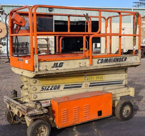
JLG CM2546 Spec Sheet
Quick-reference specifications for the JLG CM2546. Includes extracted performance, dimensions, capacities, and other details found in the source PDF.
Model: Reference PDF
BHESPECS note: Specs can vary by configuration, serial range, and market. Always confirm against the machine data plate and the source PDF.
Weights & Electrical
| FIGURE | 2-2. CONTROL VALVE ASSEMBLY – HYDRO-AIR (MACHINES WITH BANG-BANG DRIVE BUILT PRIOR TO JUNE |
|---|---|
| FIGURE | 2-4. CONTROL VALVE ASSEMBLY – HYDRO-AIR (MACHINES WITH PROPORTIONAL DRIVE) …………………………. 36 |
| Steer Cylinder Assembly – All Machines August | 1995 to Present |
| machines built May-July use 1360261 celvis, | 0961931 bushing & 4130269 spindle. (CM2033) |
| Clevis Weldment (Use | 1360261 Clevis & 0961931 Bushing as Replacement) (CM2033) |
| Clevis Welment (Use | 1360262 Clevis & 0961931 Bushing as replacement) (CM2046) |
| machines built May-July 1994 use 1360262 celvis, | 0961931 |
| Clevis Weldment (Use | 1360262 clevis & 0961931 bushing as replacement) (CM2546) |
| Clevis Weldment (Use | 1360263 clevis & 0961931 bushing as replacement) (CM2558) |
Powertrain & Systems
| FIGURE 1-3. REAR AXLE AND BRAKE INSTALLATIONS (PRIOR TO MARCH | 1992) ………………………………………………………. 14 |
|---|---|
| FIGURE 1-4. REAR AXLE AND BRAKE INSTALLATIONS (MARCH | 1992 TO PRESENT) …………………………………………………. 18 |
| FIGURE 1-1. FRAME, STEERING AND DRIVE INSTALLATION SECTION 1 – | 1 FRAME |
| FIGURE | 1-1. FRAME, STEERING AND DRIVE INSTALLATION |
| STEERING AND DRIVE INSTALLATION (STANDARD PARTS) | 101 |
| STEERING AND DRIVE INSTALLATION (PRIOR TO MARCH | 1992) (VARIABLE PARTS) (CM2033) |
| Ref STEERING AND DRIVE INSTALLATIOIN (MARCH | 1992 TO |
| Ref STEERING AND DRIVE INSTALLATIOIN AUGUST | 1994 TO |
| STEERING AND DRIVE INSTALLATION (PRIOR TO MARCH | 1992) (VARIABLE PARTS) (CM2046) |
| Ref STEERING AND DRIVE INSTALLATIOIN (AUGUST | 1994 TO |
| STEERING AND DRIVE INSTALLATION (PRIOR TO MARCH | 1992) (VARIABLE PARTS) (CM2546) |
| STEERING AND DRIVE INSTALLATION (PRIOR TO MARCH | 1992) (VARIABLE PARTS) (CM2558) |
Hydraulics & Capacities
| FIGURE | 2-5. CONTROL VALVE ASSEMBLY – HYDRO AIR (HYDRAULICALLY EXTENDED DECK OPTION) …………………….. 40 |
|---|---|
| FIGURE | 4-5. OPTIONAL HYDRAULICALLY EXTENDED DECK INSTALLATION, WITH STANDARD HANDRAILS ……………… 76 |
| FIGURE | 4-6. OPTIONAL HYDRAULICALLY EXTENDED DECK INSTALLATION, WITH FOLD-DOWN HANDRAILS ……………. 80 |
| FIGURE | 5-4. PLATFORM EXTENSION C YLINDER ASSEMBLY (HYDRAULICALLY EXTENDED DECK OPTION) (STANDARD |
Lubricants & Fluids
| Fitting, Grease (CM2033) 159 to | 161 |
|---|---|
| Fitting, Grease (CM2033) | 159 |
| Fitting, Grease (CM2046) 159 to | 161 |
| Fitting, Grease (CM2046) | 159 |
| Fitting, Grease (CM2546) 159 to | 161 |
| Fitting, Grease (CM2546) | 159 |
| Fitting, Grease (CM2558) 159 to | 161 |
Flipbook / PDF Viewer
If the embed doesn’t show, use a WordPress Shortcode block for the pdf-embedder shortcode.